Q. An op-amp based circuit is implemented as shown below.
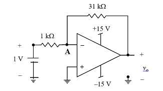
In the above circuit, assume the op-amp to be ideal. The voltage (in volts, correct to one decimal place) at node A, connected to the negative input of the op-amp as indicated in the figure is .
Ans: 0.4 – 0.6


![Determine the correctness (or otherwise) of the following Assertion [A] and the Reason [R]](https://www.gkseries.com/blog/wp-content/uploads/2023/10/Determine-the-correctness-or-otherwise-of-the-following-Assertion-A-and-the-Reason-R.jpg)