In the circuit below, the light dependent resistor (LDR) receives light from the LED. The LDR has resistances of 5 k W and 500 W under dark and illuminated conditions

Q. In the circuit below, the light dependent resistor (LDR) receives light from the LED. The LDR has resistances of 5 k W and 500 W under dark and illuminated conditions, respectively. The LED is OFF at time 𝑡 < 0. At time t = 0 s, the switch S1 is closed for 1 ms and then kept open thereafter. Assuming zero propagation delay in the devices, the LED

(A) turns ON when S1 is closed and remains ON after S1 is opened
(B) turns ON when S1 is closed and turns OFF after S1 is opened
(C) turns ON when S1 is closed and toggles periodically from ON to OFF after S1 is opened
(D) remains OFF when S1 is closed and continues to remain OFF after S1 is opened
Ans: Turns ON when S1 is closed and remains ON after S1 is opened
Sol:
When switch S1 is closed, a conducting path will be formed from Vcc to ground irrespective of the operating condition of the BJT.
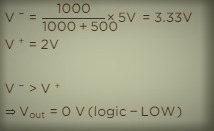
So, LED turns ON. In this situation, LDR will have a resistance of 500 Ω. Voltage at the inverting terminal of the op-amp is,

So, ¯S will be at logic – LOW and ¯R will be at logic -HIGH. It pulses Q to logic-HIGH, which cause to flow some current into the base terminal of the BJT.
When switch S1 is opened after 1 ms: Now, let us assume that LED is in OFF state.
To check the validity of this assumption, we have to check whether current is flowing into the base terminal of the BJT.
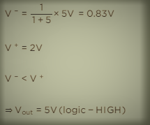
When LED is in OFF state, LDR will have a resistance of 5 kΩ.

So, ¯S will be at logic – HIGH and ¯R will be at logic -HIGH.
It pulses Q to be in previous state (i.e., logic-HIGH). This makes the transistor to be in ON state and in turn LED will be in ON state.
So, our assumption is wrong, i.e., the LED will not be in OFF state after S1 is opened. Hence LED will be in ON state both during the switch S1 is closed and after it is opened.