
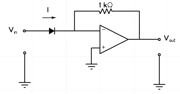
Q. In the circuit shown below, the input voltage 𝑉𝑖𝑛 is positive. The current (𝐼) – voltage (𝑉) characteristics of the diode can be assumed to be 𝐼 = 𝐼0𝑒𝑉/𝑉𝑇 under the forward bias condition, where 𝑉𝑇 is the thermal voltage and 𝐼0 is the reverse saturation current. Assuming an ideal op-amp, the output voltage 𝑉𝑜𝑢𝑡 of the circuit is proportional to
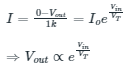
Ans: 𝑒𝑉𝑖𝑛/𝑉𝑇
Sol:

By applying KCL at node O,


![Determine the correctness (or otherwise) of the following Assertion [A] and the Reason [R]](https://www.gkseries.com/blog/wp-content/uploads/2023/10/Determine-the-correctness-or-otherwise-of-the-following-Assertion-A-and-the-Reason-R.jpg)